Cast Iron Butterfly Valves Models T-365 / T-367

Vendor: Legend Valve
Valve Type(s):
Butterfly Valves
Valve Description:
LEGEND MODELS T-365 and T-367 butterfly valves are a lug design which permits **single flange ( dead end )
installation. They also offer the same construction and features as our T-335 and T-337.
- Epoxy coated lug body allows precise positioning between flanges
- Tapped lugs and supported seat permit single-flange, "dead-end" service
- Extended neck will clear most piping insulation applications
- Bi-directional flow
- 100% Factory tested
- Rigid, phenolic-backed seat allows positive, bubble-tight shutoff
- Raised seat face eliminates the need for companion flange gaskets
- Heavy-duty lockable ten-position handle
- Models T-365AB-G and T-367AB-G are equipped with a pre-installed
- gear operator and handwheel, in place of the lever handle
Working Pressure, Non-Shock (PSI)
Cold Working Pressure (CWP): 200 psiWorking Steam Pressure (WSP): 125 psi (T-365AB & T-365AB-G Only)
Maximum service temperatures with pressures:
T-365AB & T-365AB-G: Compatible with steam up to 250° F at 125 psi or lessT-367AB & T-367AB-G: Compatible with media types other than steam up to 180° F at 200 psi or less
Special order disc options:
T-365DI &T-367DI: Ductile iron discT-365SS &T-367SS: 316 Stainless steel disc
| MATERIAL SPECIFICATION | |||||
| PART | MATERIAL | SPECIFICATION | |||
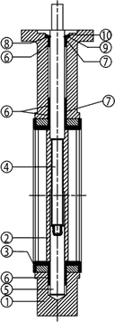 |
1 | Body | Ductile Iron, epoxy coated | ASTM A536 UNS F32800 | |
| 2 | Disc (optional disc material) (optional disc material) |
Aluminum Bronze Ductile Iron Stainless Steel |
(T-365AB, T-367AB) (T-365DI, T-367DI) (T-365SS, T-367SS) |
ASTM B148 UNS C95800 ASTM A536 UNS F32800 ASTM A351 CF8M (investment cast 316) |
|
| 3 | Seat: T-365AB & T-365AB-G T-367AB & T-367AB-G Seat backing |
EPDM Buna-N (NBR) Phenolic resin |
Commercial grade Commercial grade |
||
| 4 | Upper shaft | Stainless steel | AISI 410 stainless steel | ||
| 5 | Lower shaft | Stainless steel | AISI 410 stainless steel | ||
| 6 | Bushings (upper and lower) |
PTFE | PTFE | ||
| 7 | O-ring: T-365AB & T-365AB-G T-367AB & T-367AB-G |
EPDM Buna-N (NBR) |
Commercial grade Commercial grade |
||
| 8 | Half ring | Stainless steel | AISI 316 stainless steel | ||
| 9 | Washer | Stainless steel | AISI 316 stainless steel | ||
| 10 | Retainer ring | Stainless steel | AISI 316 stainless steel | ||
| BOLT DATA (LUG ONLY) | ||||
| VALVE SIZE | BOLT CIRCLE | BOLT SIZE | QTY | WOODRUFF SIZE |
| 2" | 4.75 | 5/8" - 11 | 4 | #3 |
| 2-1/2" | 5.50 | 5/8" - 11 | 4 | #3 |
| 3" | 6.00 | 5/8" - 11 | 4 | #3 |
| 4" | 7.50 | 5/8" - 11 | 8 | #9 |
| 5" | 8.50 | 3/4" - 10 | 8 | #9 |
| 6" | 9.50 | 3/4" - 10 | 8 | #9 |
| 8" | 11.75 | 3/4" - 10 | 8 | #9 |
| VALVE WEIGHT | ||||
| VALVE SIZE | T-335-G T-337-G | T-365-G T-367-G | T-335 T-337 | T-365 T-367 |
| 2" | 26 lbs. | 28 lbs. | 9 lbs. | 11 lbs. |
| 2-1/2" | 28 lbs. | 30 lbs. | 11 lbs. | 13 lbs. |
| 3" | 28 lbs. | 31 lbs. | 11 lbs. | 14 lbs. |
| 4" | 31 lbs.* | 38 lbs.* | 14 lbs. | 21 lbs. |
| 5" | 35 lbs.* | 43 lbs.* | 18 lbs. | 26 lbs. |
| 6" | 38 lbs.* | 46 lbs.* | 21 lbs. | 29 lbs. |
| 8" | 62 lbs.* | 74 lbs.* | 35 lbs. | 47 lbs. |
(* ) NOTE: GEAR BOX AND HANDWHEEL NOT INSTALLED
Valve Category:
Butterfly Valves
Valve Subcategory
Cast Iron - Lug Type
| Request a Quote | Request Quote |
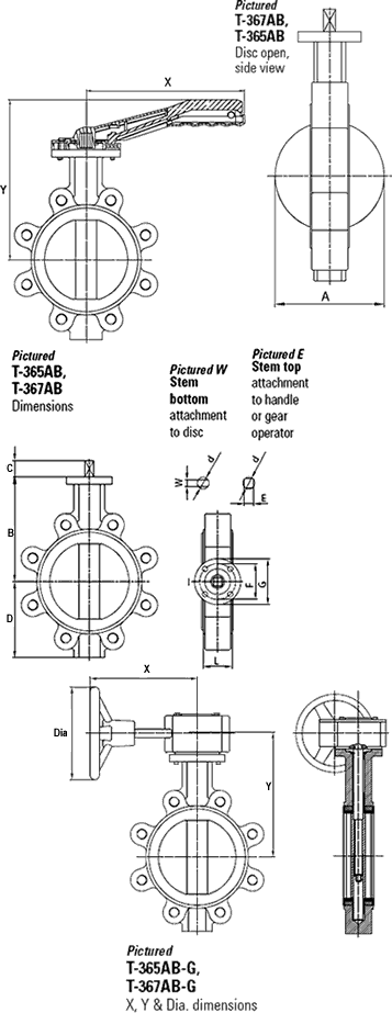
| DIMENSIONS | ||||||||
| Size | A | B | C | D | E | F* | G* | hole dia.* |
| 2" | 2.07 | 5.59 | 0.75 | 2.89 | 0.43 | 2.76 | 3.54 | 0.39 |
| 2-1/2" | 2.54 | 6.10 | 0.75 | 3.17 | 0.43 | 2.76 | 3.54 | 0.39 |
| 3" | 3.11 | 6.34 | 0.75 | 3.66 | 0.43 | 2.76 | 3.54 | 0.39 |
| 4" | 4.10 | 7.09 | 0.75 | 4.33 | 0.43 | 2.76 | 3.54 | 0.39 |
| 5" | 4.86 | 7.60 | 0.75 | 4.83 | 0.55 | 2.76 | 3.54 | 0.39 |
| 6" | 6.14 | 8.07 | 0.75 | 5.47 | 0.55 | 2.76 | 3.54 | 0.39 |
| 8" | 7.99 | 9.84 | 0.98 | 6.89 | 0.67 | 4.02 | 4.92 | 0.47 |
| 10" | 9.88 | 11.10 | 1.58 | 8.19 | 0.87 | 4.02 | 4.92 | 0.47 |
| 12" | 11.89 | 12.84 | 1.58 | 9.61 | 0.87 | 4.02 | 4.92 | 0.47 |
| Size | ISO 5211* | L | W | d | X | Y | Torque ft./lb | |
| 2" | F07 | 1.69 | 0.39 | 0.50 | 8.07 | 8.35 | 11.06 | |
| 2-1/2" | F07 | 1.81 | 0.39 | 0.50 | 8.07 | 8.86 | 12.54 | |
| 3" | F07 | 1.81 | 0.39 | 0.50 | 8.07 | 9.09 | 16.23 | |
| 4" | F07 | 2.05 | 0.47 | 0.62 | 10.04 | 10.24 | 25.08 | |
| 5" | F07 | 2.20 | 0.55 | 0.74 | 10.04 | 10.75 | 35.41 | |
| 6" | F07 | 2.20 | 0.55 | 0.74 | 10.04 | 11.22 | 53.85 | |
| 8" | F10 | 2.36 | 0.67 | 0.87 | 13.98 | 13.19 | 114.33 | |
| 10" | F10 | 2.68 | 0.87 | 1.12 | 13.98 | 14.45 | - | |
| 12" | F10 | 3.07 | 0.95 | 1.24 | 13.98 | 16.18 | - | |
*Note: This information is applicable to the actuator mounting flange portion of the valve s body
| X, Y & Dia. DIMENSIONS T-365AB-G, T-367AB-G (GEAR OPERATOR) | |||
| Size | X | Y | Dia. |
| 2" | 5.51 | 6.69 | 5.24 |
| 2-1/2" | 5.51 | 7.21 | 5.24 |
| 3" | 5.51 | 7.44 | 5.24 |
| 4" | 5.51 | 8.19 | 5.24 |
| 5" | 5.51 | 8.70 | 5.24 |
| 6" | 5.51 | 9.17 | 5.24 |
| 8" | 8.74 | 11.18 | 8.74 |
| 10” | 8.74 | 12.44 | 8.74 |
| 12” | 8.74 | 14.17 | 8.74 |
| CLASS 125/150 FLANGE DATA | ||||
| Nominal size |
Bolt circle diameter |
Bolt size |
Number of bolt holes |
Flange diameter |
| 2" | 4.75 | 5/8" - 11 | 4 | 6" |
| 2-1/2" | 5.5 | 5/8" - 11 | 4 | 7" |
| 3" | 6 | 5/8" - 11 | 4 | 7.50" |
| 4" | 7.5 | 5/8" - 11 | 8 | 9" |
| 5" | 8.5 | 3/4" - 10 | 8 | 10" |
| 6" | 9.5 | 3/4" - 10 | 8 | 11" |
| 8" | 11.75 | 3/4" - 10 | 8 | 13.50" |
| 10" | 14.25 | 7/8"- 9 | 12 | 16" |
| 12" | 17 | 7/8"- 9 | 12 | 19" |
|
|
|||||||||||||||||||||||||||||||||||||||||||||||||||||||||||||||||||||||||||||||||||||||||||||||||||||||||||||||||||||||||||||||||||||
 |
WARNING: Cancer and Reproductive Harm - www.P65Warnings.ca.gov |

