


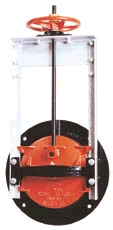
Fresno Series 6400 - 20-10C Slide Gate
Vendor: Fresno Valves & Castings
Valve Type(s):
Gate Valves
Valve Description:
Unique cross bar design provides uniform wedging action around seating surface. Roll threaded rising stem ensures ease of operation and extended stem life.
Rugged Cast Iron seat and cover. Available for mounting to headwalls or corrugated pipe. Precision machined seating surfaces.
Rated for up to 20 ft. seating head and 10 ft. unseating head.
Model 20-10C
Valve Category:
Gates & Lifts
| Request a Quote |
| Request Quote |
Pressure Rating
| Gate Size | Seating | Unseating | ||
| 8" - 12" | 35 (15.2 psi) | 10 (4.5 psi) | ||
| 14" - 18" | 32 (13.9 psi) | 10 (4.5 psi) | ||
| 8" - 12" | 35 (15.2 psi) | 10 (4.5 psi) | ||
| 14" - 18" | 32 (13.9 psi) | 10 (4.5 psi) |
Installation
The Series 6400 Slide Gate is normally installed on corrugated steel pipe or bolted to a concrete head wall or steel flange. When attached to corrugated steel pipe, the spigot back style seat is used. This style seat allows for a simple bolted connection to the pipe or use of a rod and lug harness assembly to mount the gate to the pipe. In either case, a mastic is used to seal the joint.
When mounted to a concrete headwall the flat back style seat is used in conjunction with embedded anchor bolts to locate, align and support the gate. A one inch space between the seat and concrete is grouted after the gate has been mounted on the anchor bolts. The flat back style seat can also be machined and drilled to match a partial pattern of a standard 25 lb. or 125 lb. flange.
Options
|
|
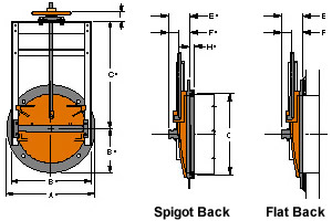
| Gate | Dimensions (inches) | Anchor Bolt Data | Lift Data | ||||||||||
| Diameter | Lift Type | Wheel Dia. | Stem Dia. | ||||||||||
| A | B | C | D | E | F | G | H | Qty. | Size | ||||
| 8" | 13.5 | 11.38 | 18 | 2.88 | 6.19 | 3 | 8.75 | 1.5 | 4 | 1/2 x 12 | H1 | 10 | 7/8 |
| 10" | 16 | 13.38 | 21 | 2.88 | 6.44 | 3 | 10.75 | 1.5 | 4 | 1/2 x 12 | H1 | 10 | 7/8 |
| 12" | 19 | 15.38 | 24 | 2.88 | 6.63 | 3 | 13.25 | 1.5 | 4 | 1/2 x 12 | H1 | 10 | 7/8 |
| 14" | 21 | 17.38 | 27 | 2.88 | 6.88 | 3.31 | 15.25 | 1.5 | 4 | 1/2 x 12 | H1 | 10 | 7/8 |
| 15" | 22 | 18.38 | 28.5 | 2.88 | 7.69 | 3.31 | 16.25 | 1.5 | 4 | 1/2 x 12 | H1 | 10 | 7/8 |
| 16" | 23.5 | 19.38 | 30 | 2.88 | 7.94 | 3.31 | 17.25 | 1.5 | 4 | 1/2 x 12 | H1 | 10 | 7/8 |
| 18" | 25 | 22.88 | 33.25 | 2.88 | 9 | 4.19 | 19.25 | 1.5 | 4 | 5/8 x 12 | H1 | 14 | 1-1/8 |
| 20" | 27.5 | 24.88 | 36.25 | 2.88 | 9.31 | 4.19 | 21.25 | 1.5 | 4 | 5/8 x 12 | H1 | 14 | 1-1/8 |
| 21" | 28.5 | 25.88 | 37.25 | 2.88 | 9.56 | 4.19 | 22.25 | 1.5 | 4 | 5/8 x 12 | H1 | 14 | 1-1/8 |
| 24" | 32 | 28.88 | 42.25 | 2.88 | 10.94 | 4.19 | 25.25 | 1.5 | 4 | 5/8 x 12 | H1 | 14 | 1-1/8 |
| 30" | 38.75 | 35.88 | 51.5 | 3.5 | 12.25 | 4.75 | 33.25 | 2 | 6 | 3/4 x 12 | H2 | 18 | 1-1/2 |
| 36" | 46 | 41.88 | 60.5 | 3.5 | 13.88 | 5 | 37.25 | 2 | 6 | 3/4 x 12 | H2 | 24 | 1-1/2 |
| 42" | 53 | 47.88 | 69.5 | 3.5 | 14.5 | 5.38 | 43.38 | 2 | 6 | 3/4 x 12 | H2 | 30 | 1-1/2 |
 |
WARNING: Cancer and Reproductive Harm - www.P65Warnings.ca.gov |