


Coupling Identification - North American
There are five coupling systems generally used for hydraulic connections today. They are identified geographically or by country as:
North American
This section lists the origin and coupling style found in each country. Brief descriptions and dimensional data follows each coupling style.
| Iron Pipe Thread Abbreviations | |||
| N | National | F | Fuels |
| P | Pipe | S | Straight Thread |
| T | Tapered Thread | M | Mechanical Joint |
NPTF
This is a dry seal thread; the National pipe tapered thread for fuels. This is used for both male and female ends.
The NPTF male will mate with the NPTF, NPSF, or NPSM female.
The NPTF male has tapered threads and a 30° inverted seat. The NPTF female has tapered threads and no seat. The seal tales place by deformation of the threads. The NPSM female has straight threads and a 30° inverted seat. The seal takes place on the 30° seat.
The NPTF connector is similar to, but not interchangeable with, the BSPT connector. The thread pitch is different in most sizes. Also, the thread angle is 60° instead of the 55° angle found on BSPT threads.
NPSF
The National pipe straight thread for fuels. This is sometimes used for female ends and properly mates with the NPTF male end. However, the SAE recommends the NPTF thread in preference to the NPSF for female ends.
NPSM
National pipe straight thread for mechanical joint. This is used on the female swivel nut of iron pipe swivel adapters. The leak-resistant joint is not made by the sealing fit of threads, but by a tapered seat in the coupling end.
NPT Pipe Thread
| Dash Size | Nominal Size in. | No. Threads per Inch | Female Thread | Male Thread |
| Thread I.D. in. | Thread O.D. in. | |||
| -2 | 1/8 | 27 | 23/64 | 13/32 |
| -4 | 1/4 | 18 | 15/32 | 35/64 |
| -6 | 3/8 | 18 | 19/32 | 43/64 |
| -8 | 1/2 | 14 | 3/4 | 27/32 |
| -12 | 3/4 | 14 | 61/64 | 1 1/16 |
| -16 | 1 | 11 1/2 | 1 13/64 | 1 5/16 |
| -20 | 1 1/4 | 11 1/2 | 1 17/32 | 1 43/64 |
| -24 | 1 1/2 | 11 1/2 | 1 25/32 | 1 29/32 |
| -32 | 2 | 11 1/2 | 2 1/4 | 2 3/8 |
*37° Flare (JIC)
The society of Automotive Engineers (SAE) specifies a 37° angle flare or seat be used with high pressure hydraulic tubing. These are commonly called JIC couplings.
The JIC 37° flare male will mate with a JIC female only. The JIC male has straight threads and a 37° flare seat. The JIC female has straight threads and a 37° flare seat. The seal is made on the 37° flare seat.
Some sizes have the same threads as the SAE 45° flare. Carefully measure the seat angle to differentiate.
*Note: Some C5, C5E and Lock-On couplings may have dual machined seats (both 37° and 45° seats).
37° Flare JIC
| Dash Size | Nominal Size in. | Thread Size | Female Thread | Male Thread |
| Thread I.D. in. | Thread O.D. in. | |||
| -2 | 1/8 | 5/16-24 | 17/64 | 5/16 |
| -3 | 3/16 | 3/8-24 | 21/64 | 3/8 |
| -4 | 1/4 | 7/16-20 | 25/64 | 7/16 |
| -5 | 5/16 | 1/2-20 | 29/64 | 1/2 |
| -6 | 3/8 | 9/16-18 | 1/2 | 9/16 |
| -8 | 1/2 | 3/4-16 | 11/16 | 3/4 |
| -10 | 5/8 | 7/8-14 | 13/16 | 7/8 |
| -12 | 3/4 | 1 1/16-12 | 31/32 | 1 1/16 |
| -14 | 7/8 | 1 3/16-12 | 1 7/64 | 1 3/16 |
| -16 | 1 | 1 5/16-12 | 1 15/64 | 1 5/16 |
| -20 | 1 1/4 | 1 5/8-12 | 1 35/64 | 1 5/8 |
| -24 | 1 1/2 | 1 7/8-12 | 1 51/64 | 1 7/8 |
| -32 | 2 | 2 1/2-12 | 2 27/64 | 2 1/2 |
*SAE (45° Flare)
A term usually applied to fittings having a 45° angle flare or seat. Soft copper tubing is generally used in such applications as it is easily flared to the 45° angle. These are for low pressure applications - such as for fuel lines and refrigerant lines.
The SAE 45° flare male will mate with an SAE 45° flare female only.
The SAE male has straight threads and a 45° flare seat. The SAE female has straight threads and a 45° flare seat. The seal is made on the 45° flare seat.
Some sizes have the same threads as the SAE 37° flare. Carefully measure the seat angle to differentiate.
*Note: Some C5, C5E, PCTS, C14, and Lock-On couplings may have dual machined seats (both 37° and 45° seats).
SAE 45° Flare
| Dash Size | Nominal Size in. | Thread Size | Female Thread | Male Thread |
| Thread I.D. in. | Thread O.D. in. | |||
| -2 | 1/8 | 5/16-24 | 17/64 | 5/16 |
| -3 | 3/16 | 3/8-24 | 21/64 | 3/8 |
| -4 | 1/4 | 7/16-20 | 25/64 | 7/16 |
| -5 | 5/16 | 1/2-20 | 29/64 | 1/2 |
| -6 | 3/8 | 5/8-18 | 9/16 | 5/8 |
| -7 | 7/16 | 11/16-16 | 5/8 | 11/16 |
| -8 | 1/2 | 3/4-16 | 11/16 | 3/4 |
| -10 | 5/8 | 7/8-14 | 13/16 | 7/8 |
| -12 | 3/4 | 1 1/16-14 | 63/64 | 1 1/16 |
| -14 | 7/8 | 1 1/4-12 | 1 11/64 | 1 1/4 |
| -16 | 1 | 1 3/8-12 | 1 19/64 | 1 3/8 |
Special Power Steering Thread End
| Dash Size | Nominal Size in. | Thread Size | Female Thread | Male Thread |
| Thread I.D. in. | Thread O.D. in. | |||
| 3/8 | 11/16 | 11/16-18 | 5/8 | 11/16 |
O-Ring Boss
The O-Ring boss male will mate with an O-Ring boss female only. The female is generally found on ports.
The male has straight threads and an O-Ring. The female has straight threads and a sealing face. The seal is made at the O-Ring on the male and the sealing face on the female.
SAE Straight Thread O-Ring Boss
| Dash Size | Nominal Size in. | Thread Size | Female Thread | Male Thread | "O" Ring Size |
| Thread I.D. in. | Thread O.D. in. | ||||
| -2 | 1/8 | 5/16-24 | 17/64 | 5/16 | - |
| -3 | 3/16 | 3/8-24 | 21/64 | 3/8 | 82500 |
| -4 | 1/4 | 7/16-20 | 25/64 | 7/16 | 82501 |
| -5 | 5/16 | 1/2-20 | 29/64 | 1/2 | 82502 |
| -6 | 3/8 | 9/16-18 | 1/2 | 9/16 | 82503 |
| -8 | 1/2 | 3/4-16 | 11/16 | 3/4 | 82504 |
| -10 | 5/8 | 7/8-14 | 13/16 | 7/8 | 82505 |
| -12 | 3/4 | 1 1/16-12 | 31/32 | 1 1/16 | 82506 |
| -14 | 7/8 | 1 3/16-12 | 1 7/64 | 1 3/16 | 82507 |
| -16 | 1 | 1 5/16-12 | 1 15/64 | 1 5/16 | 82508 |
| -20 | 1 1/4 | 1 5/8-12 | 1 35/64 | 1 5/8 | 82509 |
| -24 | 1 1/2 | 1 7/8-12 | 1 51/64 | 1 7/8 | - |
| -32 | 2 | 2 1/2-12 | 2 27/64 | 2 1/2 | - |
O-Ring Flange - SAE J518
The SAE Code 61 and Code 62 4-Bolt Split Flange is used worldwide, usually as a connection on pumps and motors.
There are three exceptions:
1. The -10 size, which is common outside of North America, is not an SAE standard size.
2. Caterpillar flanges, which are the same flange O.D. as SAE Code 62, have a thicker flange head ("C" dimension in illustration).
3. Poclain flanges, which are completely different from SAE flanges.
SAE Code 61 and Code 62
| Nominal Flange Size | Code61 (FL) | |||
| Flange O.D. | A | B | C | |
| 1/2 | 1.188 | .688 | 1.500 | .265 |
| 5/8 | 1.338 | - | - | .265 |
| 3/4 | 1.500 | .875 | 1.875 | .265 |
| 1 | 1.750 | 1.031 | 2.062 | .315 |
| 1 1/4 | 2.000 | 1.188 | 2.312 | .315 |
| 1 1/2 | 2.375 | 1.406 | 2.750 | .315 |
| 2 | 2.812 | 1.688 | 3.062 | .375 |
| 2 1/2 | 3.312 | 2.000 | 3.500 | .375 |
| 3 | 4.000 | 2.438 | 4.188 | .375 |
| 3 1/2 | 4.500 | 2.750 | 4.750 | .422 |
| 4 | 5.000 | 3.062 | 5.125 | .442 |
| 5 | 6.000 | 3.625 | 6.000 | .442 |
| Nominal Flange Size | Code62 (FLH) | |||
| Flange O.D. | A | B | C | |
| 1/2 | 1.250 | .718 | 1.594 | .305 |
| 3/4 | 1.625 | .937 | 2.000 | .345 |
| 1 | 1.875 | 1.093 | 2.250 | .375 |
| 1 1/4 | 2.125 | 1.250 | 2.625 | .405 |
| 1 1/2 | 2.500 | 1.437 | 3.125 | .495 |
| 2 | 3.125 | 1.750 | 3.812 | .495 |
| Nominal Flange Size | Caterpillar (FLC) | |||
| Flange O.D. | A | B | C | |
| 3/4 | 1.625 | .938 | 2.000 | .560 |
| 1 | 1.875 | 1.094 | 2.250 | .560 |
| 1 1/4 | 2.125 | 1.250 | 2.625 | .560 |
| 1 1/2 | 2.500 | 1.438 | 3.125 | .560 |
| 2 | 3.125 | 1.750 | 3.812 | .560 |
O-Ring Face Seal (ORFS) J1453
A seal is made when the O-ring in the male contacts the flat face on the female. Couplings are intended for hydraulic systems where elastomeric seals are acceptable to over cone leakage and leak resistance is crucial.
The solid male O-ring face seal fitting will mate with a swivel female O-ring face seal fitting only.
An O-ring rests in the O-ring groove in the male.
O-Ring Face Seal
| Dash Size | Nominal Size in. | Thread Size | Male Thread | Female Thread | "O" Ring Size |
| Thread O.D. in. | Thread I.D. in. | ||||
| -4 | 1/4 | 9/16-18 | 9/16 | 1/2 | -011 |
| -6 | 3/8 | 11/16-16 | 11/16 | 5/8 | -012 |
| -8 | 1/2 | 13/16-16 | 13/16 | 3/4 | -014 |
| -10 | 5/8 | 1-14 | 1 | 15/16 | -016 |
| -12 | 3/4 | 1 3/16-12 | 1 3/16 | 1 1/8 | -018 |
| -16 | 1 | 1 7/16-12 | 1 7/16 | 1 11/32 | -021 |
| -20 | 1 1/4 | 1 11/16-12 | 1 11/16 | 1 19/32 | -025 |
| -24 | 1 1/2 | 2-12 | 2 | 1 29/32 | -029 |
Flareless Tube
The flareless solid male will mate with a female flareless nut and compression sleeve only.
The male has straight threads and a 24 seat. The female has straight threads and has a compression sleeve for a sealing surface. The seal is made between the compression sleeve and the 24 seat on the male, and between the compression sleeve and the tubing on the female.
Flareless Tube
| Dash Size | Tube Size in. | Nominal Size in. | Thread Size | Female Thread | Male Thread |
| Thread I.D. in. | Thread O.D. in. | ||||
| -2 | 1/8 | 5/16 | 5/16-24 | 17/16 | 5/16 |
| -3 | 3/16 | 3/8 | 3/8-24 | 21/64 | 3/8 |
| -4 | 1/4 | 7/16 | 7/16-20 | 25/64 | 7/16 |
| -5 | 5/16 | 1/2 | 1/2-20 | 29/64 | 1/2 |
| -6 | 3/8 | 9/16 | 9/16-18 | 1/2 | 9/16 |
| -8 | 1/2 | 3/4 | 3/4-16 | 11/16 | 3/4 |
| -10 | 5/8 | 7/8 | 7/8-14 | 13/16 | 7/8 |
| -12 | 3/4 | 1 1/16 | 1 1/16-12 | 31/32 | 1 1/16 |
| -14 | 7/8 | 1 3/16 | 1 3/16-12 | 1 7/64 | 1 3/16 |
| -16 | 1 | 1 5/16 | 1 5/16-12 | 1 15/64 | 1 5/16 |
| -20 | 1 1/4 | 1 5/8 | 1 5/8-12 | 1 35/64 | 1 5/8 |
| -24 | 1 1/2 | 1 7/8 | 1 7/8-12 | 1 51/64 | 1 7/8 |
| -32 | 2 | 2 1/2 | 2 1/2-12 | 2 27/64 | 2 1/2 |
SAE Inverted Flare
The SAE 45° inverted flare male will mate with an SAE 42° inverted flare female only.
The male has straight threads and a 45° inverted flare. The female has straight threads and a 42° inverted flare. The seal is made on the 45° flare seat on the male and the 42° flare seat on the female.
SAE Inverted Flare
| Dash Size | Nominal Size in. | Thread Size | Female Thread | Male Thread |
| Thread I.D. in. | Thread O.D. in. | |||
| -2 | 1/8 | 5/16-28 | 9/32 | 5/16 |
| -3 | 3/16 | 3/8-24 | 21/64 | 3/8 |
| -4 | 1/4 | 7/16-24 | 25/64 | 7/16 |
| -5 | 5/16 | 1/2-20 | 29/64 | 1/2 |
| -6 | 3/8 | 5/8-18 | 37/64 | 5/8 |
| -7 | 7/16 | 11/16-18 | 5/8 | 11/16 |
| -8 | 1/2 | 3/4-16 | 45/64 | 3/4 |
| -10 | 5/8 | 7/8-18 | 13/16 | 7/8 |
| -12 | 3/4 | 1 1/16-16 | 1 | 1 1/16 |
Female Braze-On Stems
Braze-On Stems
| Dash Size | Tubing O.D. "B" (inch) |
| -4 | 1/4 |
| -5 | 5/16 |
| -6 | 3/8 |
| -8 | 1/2 |
| -10 | 5/8 |
| -12 | 3/4 |
| -16 | 1 |
| -20 | 1 1/4 |
| -24 | 1 1/2 |
Grease Fittings
Special Male Grease Fitting
Special Female Grease Fitting
Parker Triple Thread Flare Fittings
Parker Triple Thread Flare Fittings
| Dash Size | Nominal Thread Size in. | Thread Size | Male Thread | Female Thread |
| Thread O.D. in. | Thread I.D. in. | |||
| -16 | 1 5/16 | 1 5/16-14 | 1 5/16 | 1 1/4 |
| -20 | 1 5/8 | 1 5/8-14 | 1 5/8 | 1 9/16 |
| -24 | 1 7/8 | 1 7/8-14 | 1 7/8 | 1 13/16 |
| -32 | 2 1/2 | 2 1/2-12 | 2 1/2 | 1 1/4 |
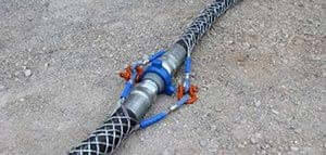
Press-Lok Connectors
Press-Lok style connectors are found on mining equipment worldwide.
The seal is made when the O-ring on the male contacts the inside surface of the female. The two connectors are held together with a staple.
Press-Lok Connectors
| Dash Size | Nominal Size in. | Male Thread | Female Thread |
| Thread O.D. in. | Thread I.D. in. | ||
| -4 | 1/4 | .39 | .40 |
| -6 | 3/8 | .55 | .56 |
| -8 | 1/2 | .70 | .71 |
| -12 | 3/4 | .94 | .95 |
| -16 | 1 | 1.22 | 1.23 |
| -20 | 1 1/4 | 1.49 | 1.50 |