Coupling Identification - German DIN (Deutsche Industrial Norme)
There are five coupling systems generally used for hydraulic connections today. They are identified geographically or by country as:
German Thread Types
Popular couplings are German DIN (Deutsche Industrial Norme). A coupling referred to as metric, usually means a DIN coupling. Flanges are standard Code 61 or Code 62 (except -10)*.
DIN 24° Cone
The DIN 24° cone male will mate with any of the three females shown.
The male has a 24° seat, straight metric threads, and a recessed counter bore which matches the tube O.D. of the coupling used with it. The mating female is a 24° cone with O-ring, a metric tube fitting or a universal 24° or 60° cone.
There is a light and heavy series DIN coupling. Proper identification is made by measuring both the thread size and the tube O.D. (The heavy series has a smaller tube O.D. than the light, but has a thicker wall section.)
When measuring the flare angle with the seat angle gauge, use the 12° gauge. (The seat angle gauge measures the angle from the connector centerline.)
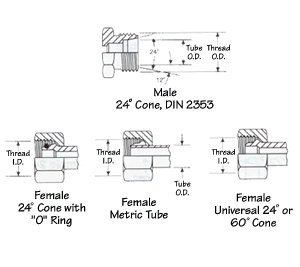
DIN 24° male and Mating Females
| Metric Thread Size | Male Thread O.D. mm | Female Thread I.D. mm | Tube O.D. Light Series mm | Tube O.D. Heavy Series mm |
| M12x1.5 | 12.0 | 10.5 | 6 | - |
| M14x1.5 | 14.0 | 12.5 | 8 | - |
| M16x1.5 | 16.0 | 14.5 | 10 | 8 |
| M18x1.5 | 18.0 | 16.5 | 12 | 10 |
| M20x1.5 | 20.0 | 18.5 | 14 | 12 |
| M22x1.5 | 22.0 | 20.5 | 15 | 14 |
| M24x1.5 | 24.0 | 22.5 | - | 16 |
| M26x1.5 | 26.0 | 24.5 | 18 | - |
| M30x2.0 | 30.0 | 28.0 | 22 | 20 |
| M36x2.0 | 36.0 | 34.0 | 28 | 25 |
| M42x2.0 | 42.0 | 40.0 | - | 30 |
| M45x2.0 | 45.0 | 43.0 | 35 | - |
| M52x2.0 | 52.0 | 50.0 | 42 | 38 |
DIN 60° Cone
The DIN 60° cone male will mate with the female universal 24° or 60° cone connector only.
The male has a 60° seat and straight metric threads. The female has a 24° and 60° universal seat and straight metric threads.
When measuring the flare angle with the seat angle gauge, use the 30° gauge. (The seat angle gauge measures the angle from the connector centerline.)
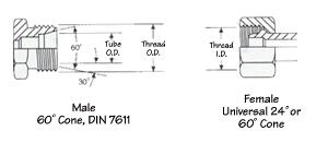
DIN 60° Male and Mating Female
| Metric Thread Size | Male Thread O.D. mm | Female Thread I.D. mm | Tube O.D. mm |
| M12x1.5 | 12.0 | 10.5 | 6 |
| M14x1.5 | 14.0 | 12.5 | 8 |
| M16x1.5 | 16.0 | 14.5 | 10 |
| M18x1.5 | 18.0 | 16.5 | 12 |
| M20x1.5 | 20.0 | 18.5 | 14 |
| M22x1.5 | 22.0 | 20.5 | 15 |
| M24x1.5 | 24.0 | 22.5 | - |
| M26x1.5 | 26.0 | 24.5 | 18 |
| M30x2.0 | 30.0 | 28.0 | 22 |
DIN 3852 Couplings Type A & B
(Parallel Threads)
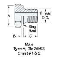
The male DIN 3852 Type A & B couplings will mate with the female DIN coupling shown below.
The male and female type A & B couplings have straight threads. Sheet 1 refers to straight metric threads, and sheet 2 refers to straight Whitworth threads. The seal occurs when the ring seal (Type A) or the face seal (Type B) mates with the face of the female port.
These are two series of DIN 3852 Type A & B couplings, the light (L) and the heavy (S) series.
 | 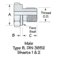 |
| Series | Tube O.D. mm | Male Metric Thread Parallel DIN 3852 Type A & B Sheet 1 | Male Whitworth Thread Parallel DIN 3852 Type A & B Sheet 2 | ||||||||
| Metric Thread Size | Thread O.D. mm | A mm | B mm | C mm | Whitworth Thread Size | Thread O.D. in | A mm | B mm | C mm | ||
L Light | 6 | 10x1 | 10 | 14 | 1.5 | 8 | 1/8-28 | 3/8 | 14 | 1.5 | 8 |
| 8 | 12x1.5 | 12 | 17 | 2.0 | 12 | 1/4-19 | 1/2 | 17 | 2.0 | 12 | |
| 10 | 14x1.5 | 14 | 19 | 2.0 | 12 | 1/4-19 | 1/2 | 19 | 2.0 | 12 | |
| 12 | 16x1.5 | 16 | 21 | 2.5 | 12 | 3/8-19 | 21/32 | 21 | 2.5 | 12 | |
| 15 | 18x1.5 | 18 | 23 | 2.5 | 12 | 1/2-14 | 13/16 | 23 | 2.5 | 12 | |
| 18 | 22x1.5 | 22 | 27 | 3.0 | 14 | 1/2-14 | 13/16 | 27 | 3.0 | 14 | |
| 22 | 26x1.5 | 26 | 31 | 3.0 | 16 | 3/4-14 | 11/32 | 31 | 3.0 | 16 | |
| 28 | 33x2 | 33 | 39 | 3.0 | 18 | 1-11 | 15/16 | 39 | 3.0 | 18 | |
| 35 | 42x2 | 42 | 49 | 3.0 | 20 | 11/4-11 | 121/32 | 49 | 3.0 | 20 | |
| 42 | 48x2 | 48 | 55 | 3.0 | 22 | 11/2-11 | 17/8 | 55 | 3.0 | 22 | |
S Heavy | 6 | 12x1.5 | 12 | 17 | 2.0 | 12 | 1/4-19 | 1/2 | 17 | 2.0 | 12 |
| 8 | 14x1.5 | 14 | 19 | 2.0 | 12 | 1/4-19 | 1/2 | 19 | 2.0 | 12 | |
| 10 | 16x1.5 | 16 | 21 | 2.5 | 12 | 3/8-19 | 21/32 | 21 | 2.5 | 12 | |
| 12 | 18x1.5 | 18 | 23 | 2.5 | 12 | 3/8-19 | 21/32 | 23 | 2.5 | 12 | |
| 14 | 20x1.5 | 20 | 25 | 3.0 | 14 | 1/2-14 | 13/16 | 25 | 3.0 | 14 | |
| 16 | 22x1.5 | 22 | 27 | 3.0 | 14 | 1/2-14 | 13/16 | 27 | 3.0 | 14 | |
| 20 | 27x2 | 27 | 32 | 3.0 | 16 | 3/4-14 | 11/32 | 32 | 3.0 | 16 | |
| 25 | 33x2 | 33 | 39 | 3.0 | 18 | 1-11 | 15/16 | 39 | 3.0 | 18 | |
| 30 | 42x2 | 42 | 49 | 3.0 | 20 | 11/4-11 | 121/32 | 49 | 3.0 | 20 | |
| 38 | 48x2 | 48 | 55 | 3.0 | 22 | 11/2-11 | 17/8 | 55 | 3.0 | 22 | |
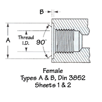
| Female Metric Thread Parallel DIN 3852 Type A & B Sheet 1 | Female Metric Thread Parallel DIN 3852 Type A & B Sheet 2 | ||||||
| Metric Thread Size | Thread O.D. mm | A mm | B mm | Whitworth Thread Size | Thread O.D. in | A mm | B mm |
| 10x1 | 8.5 | 15 | 1.0 | 1/8-28 | 11/32 | 15 | 1.0 |
| 12x1.5 | 10.5 | 18 | 1.5 | 1/4-19 | 15/32 | 19 | 1.5 |
| 14x1.5 | 12.5 | 20 | 1.5 | 1/4-19 | 15/32 | 19 | 1.5 |
| 16x1.5 | 14.5 | 22 | 1.5 | 3/8-19 | 19/32 | 23 | 2.0 |
| 18x1.5 | 16.5 | 24 | 2.0 | 1/2-14 | 3/4 | 27 | 2.5 |
| 22x1.5 | 20.5 | 28 | 2.5 | 1/2-14 | 3/4 | 27 | 2.5 |
| 26x1.5 | 24.5 | 32 | 2.5 | 3/4-14 | 31/32 | 33 | 2.5 |
| 33x2 | 31.5 | 40 | 2.5 | 1-11 | 17/32 | 40 | 2.5 |
| 42x2 | 40.5 | 50 | 2.5 | 11/4-11 | 117/32 | 50 | 2.5 |
| 48x2 | 46.5 | 56 | 2.5 | 11/2-11 | 125/32 | 56 | 2.5 |
| 12x1.5 | 10.5 | 18 | 1.5 | 1/4-19 | 15/32 | 19 | 1.5 |
| 14x1.5 | 12.5 | 20 | 1.5 | 1/4-19 | 15/32 | 19 | 1.5 |
| 16x1.5 | 14.5 | 22 | 1.5 | 3/8-19 | 19/32 | 23 | 2.0 |
| 18x1.5 | 16.5 | 24 | 2.0 | 3/8-19 | 19/32 | 23 | 2.0 |
| 20x1.5 | 18.5 | 26 | 2.0 | 1/2-14 | 3/4 | 27 | 2.5 |
| 22x1.5 | 20.5 | 28 | 2.5 | 1/2-14 | 3/4 | 27 | 2.5 |
| 27x2 | 25.5 | 33 | 2.5 | 3/4-14 | 31/32 | 33 | 2.5 |
| 33x2 | 31.5 | 40 | 2.5 | 1-11 | 17/32 | 40 | 2.5 |
| 42x2 | 40.5 | 50 | 2.5 | 11/4-11 | 117/32 | 50 | 2.5 |
| 48x2 | 46.5 | 56 | 2.5 | 11/2-11 | 125/32 | 56 | 2.5 |
DIN 3852 Type C Sheets 1 & 2 Metric and Whitworth Tapered Thread Connectors
The DIN 3852 Type C couplings are available with either metric or Whitworth British thread. The male will mate only with the female as shown.
The male and female couplings have tapered threads. Sheet 1 refers to tapered metric threads, and Sheet 2 refers to tapered Whitworth threads. The seal takes place on the threads.
There are three series of DIN 3852 Type C couplings: extra light (LL), light (L) and heavy (S).
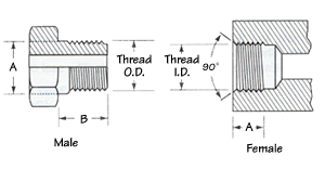
DIN 3852 Type C Sheets 1 & 2 Metric and Whitworth Tapered Thread Connectors
| Series | Tube O.D. mm | Male DIN3852 Type C, Sheet 1 Metric Tapered Threads | Male DIN 3852 Type C, Sheet 2 Whitworth Tapered Threads | ||||||
| Metric Thread Size | A mm | B mm | Thread O.D. mm | Whitworth Thread Size | A in | B mm | Thread O.D. in | ||
LL Extra Light | 4 | 8x1 | 8.40 | 8 | 8 | 1/8-28 | .392 | 8 | 1/8 |
| 5 | 8x1 | 8.40 | 8 | 8 | 1/8-28 | .392 | 8 | 1/8 | |
| 6 | 10x1 | 10.40 | 8 | 10 | 1/8-28 | .392 | 8 | 1/8 | |
| 8 | 10x1 | 10.40 | 8 | 10 | 1/8-28 | .392 | 8 | 1/8 | |
L Light | 6 | 10x1 | 10.40 | 8 | 10 | 1/8-28 | .392 | 8 | 1/8 |
| 8 | 12x1.5 | 12.53 | 12 | 12 | 1/4-19 | .532 | 12 | 1/4 | |
| 10 | 14x1.5 | 14.53 | 12 | 14 | 1/4-19 | .532 | 12 | 1/4 | |
| 12 | 16x1.5 | 16.53 | 12 | 16 | 3/8-19 | .670 | 12 | 3/8 | |
| 15 | 18x1.5 | 18.53 | 12 | 18 | 1/2-14 | .839 | 14 | 1/2 | |
| 18 | 22x1.5 | 22.65 | 14 | 22 | 1/2-14 | .839 | 14 | 1/2 | |
S Heavy | 6 | 12x1.5 | 12.53 | 12 | 12 | 1/4-19 | .532 | 12 | 1/4 |
| 8 | 14x1.5 | 14.53 | 12 | 14 | 1/4-19 | .532 | 12 | 1/4 | |
| 10 | 16x1.5 | 16.53 | 12 | 16 | 3/8-19 | .670 | 12 | 3/8 | |
| 12 | 18x1.5 | 18.53 | 12 | 18 | 3/8-19 | .670 | 12 | 3/8 | |
| 14 | 20x1.5 | 20.65 | 14 | 20 | 1/2-14 | .839 | 14 | 1/2 | |
| 16 | 22x1.5 | 22.65 | 14 | 22 | 1/2-14 | .839 | 14 | 1/2 | |
| Female DIN 3852 Type C, Sheet 1 Metric Tapered Threads | Female DIN 3852 Type C, Sheet 2 Whitworth Tapered Threads | ||||
| Metric Thread Size | Thread I.D. mm | A mm | Whitworth Thread Size | Thread I.D. in | A mm |
| 8x1 | 6.5 | 5.5 | 1/8-28 | 11/32 | 5.5 |
| 8x1 | 6.5 | 5.5 | 1/8-28 | 11/32 | 5.5 |
| 10x1 | 8.5 | 5.5 | 1/8-28 | 11/32 | 5.5 |
| 10x1 | 8.5 | 5.5 | 1/8-28 | 11/32 | 5.5 |
| 10x1 | 8.5 | 5.5 | 1/8-28 | 11/32 | 5.5 |
| 12x1.5 | 10.5 | 8.5 | 1/4-19 | 15/32 | 8.5 |
| 14x1.5 | 12.5 | 8.5 | 1/4-19 | 15/32 | 8.5 |
| 16x1.5 | 14.5 | 8.5 | 3/8-19 | 19/32 | 8.5 |
| 18x1.5 | 16.5 | 8.5 | 1/2-14 | 3/4 | 8.5 |
| 22x1.5 | 20.5 | 10.5 | 1/2-14 | 3/4 | 10.5 |
| 12x1.5 | 10.5 | 8.5 | 1/4-19 | 15/32 | 8.5 |
| 14x1.5 | 12.5 | 8.5 | 1/4-19 | 15/32 | 8.5 |
| 16x1.5 | 14.5 | 8.5 | 3/8-19 | 19/32 | 8.5 |
| 18x1.5 | 16.5 | 8.5 | 3/8-19 | 19/32 | 8.5 |
| 22x1.5 | 20.5 | 10.5 | 1/2-14 | 3/4 | 10.5 |
Metric Standpipe Assembly
A metric standpipe assembly is comprised of three components attached to a male fitting. The components are: a Standpipe, Bite Sleeve and Metric Nut. The nut is placed over the Standpipe, followed by the Bit Sleeve (see illustration below). For DIN light assemblies, a DIN light metric nut is used. For DIN heavy assemblies, a DIN heavy metric nut is used. The Bit Sleeve and Standpipe are selected on the basis of tube O.D. required.
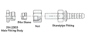
Metric Standpipe Assembly
| Metric Standpipe DIN Tube O.D. mm | Bit Sleeve DIN Tube O.D. mm | Metric Nut Thread | |
| Light | Heavy | ||
| 6 | 6 | M12x1.5 | - |
| 8 | 8 | M14x1.5 | M16x1.5 |
| 10 | 10 | M16x1.5 | M18x1.5 |
| 12 | 12 | M18x1.5 | M20x1.5 |
| 15 | 15 | M22x1.5 | - |
| 16 | 16 | - | M24x1.5 |
| 18 | 18 | M26x1.5 | - |
| 20 | 20 | - | M30x2.0 |
| 22 | 22 | M30x2.0 | - |
| 25 | 25 | - | M36x2.0 |
| 28 | 28 | M36x2.0 | - |
| 30 | 30 | - | M42x2.0 |
| 35 | 35 | M45x2.0 | - |
| 38 | 38 | - | M52x2.0 |
| 42 | 42 | M52x2.0 | - |

